Home
/ Astable 555 Timer Schematic : 555 Timer 50 Duty Cycle Astable Multivibrator Control Voltage Set To Vcc 38 Khz Multisim Live : This tutorial provides sample circuits to set up a 555 timer in monostable, astable, and bistable modes as well as an in depth discussion of how the 555 timer works and how to choose components to use with it.
Astable 555 Timer Schematic : 555 Timer 50 Duty Cycle Astable Multivibrator Control Voltage Set To Vcc 38 Khz Multisim Live : This tutorial provides sample circuits to set up a 555 timer in monostable, astable, and bistable modes as well as an in depth discussion of how the 555 timer works and how to choose components to use with it.
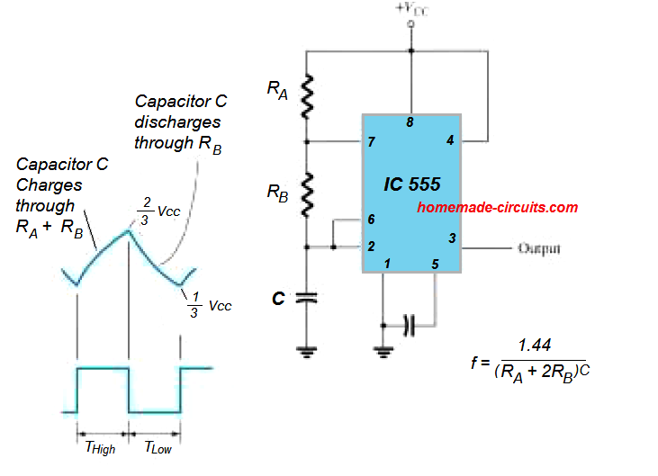
Astable 555 Timer Schematic : 555 Timer 50 Duty Cycle Astable Multivibrator Control Voltage Set To Vcc 38 Khz Multisim Live : This tutorial provides sample circuits to set up a 555 timer in monostable, astable, and bistable modes as well as an in depth discussion of how the 555 timer works and how to choose components to use with it.. Apr 07, 2021 · in order to achieve pulse position modulation, two 555 timer ic's are used in which one operates in astable mode and the other in monostable mode. That is where you get your timing for how long the output is high (pin 3) and how long it takes to go low. If you are driving an led by pulling it's anode end up to (approx.) vcc, you cannot get a short blink followed by a longer off time without a trick. Features of 555 timer ic. May 29, 2021 · in this schematic ra and rb control the longer charging time of the capacitor.
However, unless a circuit is affected by the difference between 50 percent and 50.34 percent at 1 hertz in the example then a 555 should work just fine in a circuit. We can use the 555 as a timer for up to 10 minutes. Discharging the cap is through rb. Its not listed anymore, but i can still link it in. Apr 15, 2020 · people know it as the 555 timer ic.
Kynix Semiconductor 第3页 Electronics from facebookcomshaynechen79.files.wordpress.com Just check the pinouts of the pot. The output of this ic 555 is a pulse width modulated wave. The modulating signal is applied at the pin 5 of the first ic 555 that is operating in astable mode. The timer ic is set up to work in either of the two modes. It requires only two extra components to make it work as a monostable multivibrator: The basic astable 555 timer cannot produce a 50 percent duty cycle. Jun 10, 2021 · there is a 555 timer application on this site to achieve the timings you need. Its not listed anymore, but i can still link it in.
The timer ic is set up to work in either of the two modes.
If you are driving an led by pulling it's anode end up to (approx.) vcc, you cannot get a short blink followed by a longer off time without a trick. This circuit is also called a delay. Jun 10, 2021 · there is a 555 timer application on this site to achieve the timings you need. Discharging the cap is through rb. The timer ic is set up to work in either of the two modes. A resistor and a capacitor. Learn by doing is the best. The 555 timer is a chip that can be us… Its not listed anymore, but i can still link it in. That is where you get your timing for how long the output is high (pin 3) and how long it takes to go low. Apr 07, 2021 · in order to achieve pulse position modulation, two 555 timer ic's are used in which one operates in astable mode and the other in monostable mode. Simple ne555 ic tester circuit diagram It requires only two extra components to make it work as a monostable multivibrator:
Its not listed anymore, but i can still link it in. That is, the output always is high longer than it is low. May 29, 2021 · in this schematic ra and rb control the longer charging time of the capacitor. We can use the 555 as a timer for up to 10 minutes. The 555 timer chip is just a voltage divider with a built in switch.
Astable 555 Circuit Not Oscillating Electrical Engineering Stack Exchange from i.stack.imgur.com This tutorial provides sample circuits to set up a 555 timer in monostable, astable, and bistable modes as well as an in depth discussion of how the 555 timer works and how to choose components to use with it. The basic astable 555 timer cannot produce a 50 percent duty cycle. As the name specifies, a monostable multivibrator has only one stable state. Apr 07, 2021 · in order to achieve pulse position modulation, two 555 timer ic's are used in which one operates in astable mode and the other in monostable mode. May 29, 2021 · in this schematic ra and rb control the longer charging time of the capacitor. The 555 timer is a chip that can be us… Just check the pinouts of the pot. The output of this ic 555 is a pulse width modulated wave.
Features of 555 timer ic.
A resistor and a capacitor. That is, the output always is high longer than it is low. Just check the pinouts of the pot. This circuit is also called a delay. Jun 10, 2021 · there is a 555 timer application on this site to achieve the timings you need. We can use the 555 as a timer for up to 10 minutes. May 29, 2021 · in this schematic ra and rb control the longer charging time of the capacitor. If you are driving an led by pulling it's anode end up to (approx.) vcc, you cannot get a short blink followed by a longer off time without a trick. Features of 555 timer ic. Learn by doing is the best. The output of this ic 555 is a pulse width modulated wave. Apr 15, 2020 · people know it as the 555 timer ic. This tutorial provides sample circuits to set up a 555 timer in monostable, astable, and bistable modes as well as an in depth discussion of how the 555 timer works and how to choose components to use with it.
If you are driving an led by pulling it's anode end up to (approx.) vcc, you cannot get a short blink followed by a longer off time without a trick. The timer ic is set up to work in either of the two modes. A resistor and a capacitor. The 555 timer chip is just a voltage divider with a built in switch. As the name specifies, a monostable multivibrator has only one stable state.
Ic 555 Astable Calculator from www.homemade-circuits.com This circuit is also called a delay. Jan 13, 2016 · the standard 555 astable circuit has a minimum duty cycle of 50%. The 555 timer is a chip that can be us… It requires only two extra components to make it work as a monostable multivibrator: This is the basic mode of operation of the ic 555. Just check the pinouts of the pot. The 555 timer chip is just a voltage divider with a built in switch. Jun 16, 2015 · the following figure is the schematic of ic 555 as a monostable multivibrator.
Jun 10, 2021 · there is a 555 timer application on this site to achieve the timings you need.
As the name specifies, a monostable multivibrator has only one stable state. That is where you get your timing for how long the output is high (pin 3) and how long it takes to go low. The output of this ic 555 is a pulse width modulated wave. Features of 555 timer ic. Just check the pinouts of the pot. Learn by doing is the best. May 29, 2021 · in this schematic ra and rb control the longer charging time of the capacitor. It requires only two extra components to make it work as a monostable multivibrator: The timer ic is set up to work in either of the two modes. Jun 16, 2015 · the following figure is the schematic of ic 555 as a monostable multivibrator. A resistor and a capacitor. We can use the 555 as a timer for up to 10 minutes. If you are driving an led by pulling it's anode end up to (approx.) vcc, you cannot get a short blink followed by a longer off time without a trick.
Apr 07, 2021 · in order to achieve pulse position modulation, two 555 timer ic's are used in which one operates in astable mode and the other in monostable mode 555 timer schematic. Features of 555 timer ic.